Showing posts with label software. Show all posts

Friday, May 8, 2020

Sloper Antenna for 20 m thru 10 m

A sloper dipole antenna is planned for evaluation at W4UOA to supplement the two horizontal dipoles and one horizontal loop antenna. The hyperlink in the previous sentence has a very nice analysis of the sloper antenna. I offered to do some modeling of the new antenna at W4UOA, and some results are presented below. The antenna is sized (length = 29 ft)  according to W8JI guidelines for a multi-band dipole. The radiation plots are oriented for a westward direction of greatest gain. The heights of the antenna ends and the slope angle are arbitrary starting points. The antenna is to be fed with 450-ohm balanced line that transitions to 50-ohm coax cable thru a balun.

Click on any plot to magnify.

This plot shows the total gain (horizontal and vertical polarization) of the antenna at 14.25 MHz in the horizontal plane. The blue curve maps the gain (dBi), with the scale progressing outward from the center of the plot. The labels around the plot are azimuth, like compass bearings, going clockwise around the circle. 0º is North. The antenna is in the plane oriented east-west. The maximum gain is 2.25 dBi at azimuth 334º.


This plot presents the total gain in the vertical plane. The labels around the circle are elevation (above horizon) angles. This shows the maximum gain (2.25 dBi) occurring at 46º at azimuth 338º.


This plot shows the vertical gain in the horizontal plane. The maximum gain is 2.11 dBi at azimuth 270º and elevation angle 72º.


Here is a 3D view of total gain with colors to signify the gain according to the scale at the left side of the figure. The slanted white line represents the antenna structure. The web link at the top of this article has a very nice animation of 3D and 2D views showing how the gain varies with the angle of the antenna from vertical to horizontal. The author of the article uses the same modeling software as I have used for these plots.


The W8JI article with guidelines for multi-band dipoles recommends balanced feed line of 300-ohm characteristic impedance.  Since Carl has 450-ohm balanced line on hand, I ran comparisons of the design using both feed line types, for the frequency range of interest -- 14 to 30 MHz. The modeling software generated tables of data including: SWR, gain F/B ratio,impedance (R, X, |Z|, phase). I made graphs to compare the SWR vs frequency and impedance (magnitude) vs frequency for both feed line impedance values. The graphs below show that for most frequencies there is not a large difference between the results of the two impedance values.  The SWR data are based on a 50-ohm source impedance. These results do not include the coax cable that will extend the balanced line to the antenna tuner. That detail can be added to the model at any time.


I would prefer to start these graphs at 14 MHz, but I don't know how to prevent Excel from starting at zero on the x-axis.


It will be interesting to see how this new antenna performs at W4UOA in comparison with the other antennas.

73,
John WA5MLF


Sunday, February 24, 2019

Chat Room Tips

Here are a few tips about use of the new chat room:

Right after you log in, the window below displays briefly. Note the short-cut keys for quickly switching chat rooms. You can also use the 3-dot menu and click on the chat room that you want to use.


You can identify which chat room you are currently using by looking at the colored stripe at the top of the chat window. See the two cases below.


Also, note that the chat time stamps do not identify the date. If there a few entries on consecutive days it is hard to be sure when the date has changed.

John WA5MLF


Thursday, April 5, 2018

Remote Station Operation

Here are two articles, with diagrams, that I wrote recently for use in the RV Service Net newsletter.  Any feedback and suggestions are welcome.


Many regulars on the RV Service Net recall that John, W4BXI, served as the second hour net control station on Thursdays, operating from his home at Fort Payne, AL. After moving to Asheville, NC, he now lives in an apartment that has no provisions for HF radio operation. John’s friend Carl, W4UOA, (at Mentone, AL) established a new remote interface to his own station for John to try from his new home. Carl has used other configurations of remote access to his station over a number of years.

Initially John used a single laptop PC, equipped with free software from RemoteHams.com to connect to Carl’s station. After getting familiar with the software interface (RCForb client), and finding it satisfactory for continuing his presence on HF radio, John resumed operation as a net control station. W4UOA is an excellent station for John’s participation in the RV Service Net.

Over a short period of time, John discovered other stations that are using the same RemoteHams software. This provided an opportunity to access other receiving locations, to hear stations that are too close to W4UOA for good reception during the early morning propagation on 40 m. John accessed the Richmond, VA, club station W4FJ that is available for receiving and transmitting, for club members. John also added receive capability provided by his RV Service Net friend Dan, KC4GO, of Casselberry, FL .

Around the same time John asked if my station in Baton Rouge, LA might be able to provide transmit / receive operation using the RemoteHams software. Previously I sometimes provided receive audio from my transceiver to John via a web interface (Google Hangouts), during his time slot on the RV Service Net. I set up the needed RCForb server software on my Windows PC that operates my Flex-3000 transceiver. This enabled John to use another remote station farther to the southwest.

The diagram below shows the current group of remote stations (in 4 states) that John uses from his operating location in North Carolina. Although these remote stations make it easier to hear reports from the many stations that check in, they don’t replace the excellent help provided by relay stations who are often located in even better locations for hearing and talking to the widely-distributed participants.
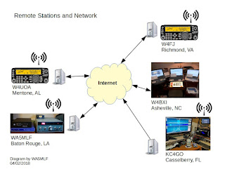
Click above to enlarge.

In a separate article I will provide additional details about how the RemoteHams software connects to radio equipment and the Internet.

John Krupsky, WA5MLF


W4BXI and friends have tested various software and hardware approaches during the past several years for remote operation of ham radio stations. We are currently using software from RemoteHams.com. In a single software package, RemoteHams includes both rig control (along with CW keying, memories and DX spotting) and audio transport. Some previous approaches have required the use of separate audio transport (e.g. Skype) and control software.

The RemoteHams software was designed to interface with the Elecraft K3 transceiver, but currently supports many other brands and models. A single, universal interface is provided for control of any supported transceiver.

For anyone thinking about remote station operation we suggest installing the free RemoteHams (RCForb) client program and using it to listen to any of the online stations listed in the RemoteHams directory. You can find many on this Online Map. The client software runs on Windows computers and Android devices. The RCForb client enables the remote operator to receive and transmit (depending on permissions granted by the station owner) and to select frequencies, modes, power levels and other parameters that are configured at the remote station. The diagram below shows the components at the location of a remote operator. The Documentation section has a good “getting started guide” along with client and server manuals. 
 
Click above to enlarge.

The diagram also shows a RemoteHams server that is used for:
  • registration and authentication of licensed remote operators
  • publishing a directory of online stations that can be used with the RemoteHams software
The server is contacted each time a remote station’s server software or a remote operator’s client software is started, but is not involved in the client-server traffic.

A remote station is not required to be listed online. Many owners of remote stations choose to operate on a non-listed basis, but can allow their friends or club members to access their station with a non-listed link.

To set up a station for remote operation requires interfacing a (supported) transceiver to a Windows computer that is running the free RCForb server program. The diagram below shows the components at the location of a remotely-controlled station. Transceiver interfacing for operating the many digital modes (PSK, FT8, etc.) provides the same capabilities needed for the RCForb server program.

If you decide to explore this mode of operation, we recommend consulting the server manual in the Documentation section and the Support Forum section of RemoteHams.com for additional documentation and tips from other users. The RemoteHams software also provides remote operation of supported amplifiers, antenna tuners and rotators.

Other topics that must be considered for the establishment of a remotely-operated station include:
  • Control of electrical power to radio and computer equipment
  • Ability of radio and computer equipment and software to restart if power is interrupted
  • Protection from lightning and electrical surges
  • Remote access to the server computer if changes to the server software settings are needed
Remote control software provided by the radio manufacturers for their radio products may provide additional capabilities that are not available through the RemoteHams software, such as SDR panadapter views. We suggest that you evaluate the capabilities of any remote control solution that control your radio equipment, and decide based on features that are most important to you.

John Krupsky, WA5MLF

Wednesday, February 14, 2018

Sampling of Group Videos & Screen Shares

While browsing through some files on an older hard drive I found some collected screen shots of some past group videos and screen shares that were common among our group members on morning QSOs. Below is a sampling of these, in order by date, starting in 2009.  The file name of each image shows the date of capture. The newest screen shot is from July of 2017.

Our group sessions made use of three services: Adobe ConnectNow (free for a limited time), Skype and Google Hangouts. Some of the later screen shots show that it is possible to participate in two separate sessions simultaneously on the same computer. In that case it is good to keep track of the microphone muting in each session window.

I added text notations to some of the views. Click on any image below to see an expanded view.


73,
John WA5MLF


Friday, December 11, 2015

HF Radio Propagation Modeling


Today's antenna modeling programs, like EZNEC and 4nec2, use the decades-old NEC program code to calculate the electric and magnetic fields produced by an antenna in 3 dimensions. (They also model parameters like impedance to assess the power efficiency of the antenna and transmission line combination.) We normally look at the radiation pattern results for the far field, considered to be greater than 2 wavelengths away from the antenna. NEC-based software is not equipped to model the fields at a great distance. The software does not model what happens to the electromagnetic energy as it propagates over a long distance.

To complete the picture of radio communication between two HF transceivers we need to look at radio propagation tools. Here are two links that list some of the available resources:
Both links make reference to VOACAP, which I became aware of while using 4nec2. I have not yet tried to use it, but I saw that VOACAP has both online and downloadable versions. 4nec2 has a utility for exporting an antenna design in the format required by VOACAP to model the propagation. Common pre-built antenna models can also be used as inputs to VOACAP. For point-to-point propagation modeling the design of the antenna at each end should be known. The first link above has a nice primer on VOACAP and a quick guide with lots of information.

The second link above also lists a program HFWIN32 which is said to contain 32-bit versions of three published propagation modeling tools: ICEPAC, VOACAP and REC533. Some more recent instructions and links are available at this web site.

A newer, freeware program HamCAP is designed to interface with VOACAP to predict HF radio propagation.

Playing with these propagation models may contribute to a better understanding of which antenna types should work best for a given frequency, time of day, geographic locations and solar conditions.
 

Friday, October 30, 2015

Google Hangout Setup for Radio Patch

This document presents the steps for setting up a Google Hangout for voice patching to a transceiver or other applications. It assumes that you have already established the required transmit and receive audio interfaces between a transceiver and a computer that runs the Google Hangout Internet application. It is convenient for the control operator of the transceiver to join the Hangout with a separate computer, tablet or smart phone for the purpose of monitoring the patch audio and speaking to other participants on the Hangout.
Updated 11/02/2015

Sunday, October 18, 2015

TPWINLOG File Locations

If you are using Windows 7 or Windows 10, and:
  • if you directed the TPWINLOG 2015 program to install in C:\TPQ then all the files you need (including TPLogOut.txt if you print to file) will be located in that folder.
  • if you allowed TPWINLOG 2015 to install in the default folder:
    C:\Program Files (x86)\TPQ
    then your files (including TPLogOut.txt if you print to file) will be located at:
    C:\Users\name\AppData\Local\VirtualStore\Program Files (x86)\TPQ
    where 'name' is the Windows user name under which the program was run.
In Windows 7, if you navigate to the program's folder C:\Program Files (x86)\TPQ
you can reach the data folder by clicking on Compatibility files, as shown in the screen shot below.


click above to enlarge
The Compatibility files button shown above for Windows 7 does not appear to be available in Windows 10, but you can open the file explorer at C:\Users and 'drill down' to 
C:\Users\name\AppData\Local\VirtualStore\Program Files (x86)\TPQ
where 'name' is the Windows user name under which the program was run.

Another option is to search for tpqsolog using the search box near the upper right corner of the file explorer in either version of Windows. However, since AppData is a hidden folder, you may need to start your search there, rather than at a higher level in the folder (directory) tree. I found that a standard (non-admin) user search starting at C:\Users would not find the file tpqsolog.txt, but the same search starting from C:\Users\name\AppData does find the file.

Wednesday, April 1, 2015

TPWINLOG Data Files

TPWINLOG 2015 creates the following data files to accomplish logging and scoring for the Telephone Pioneer QSO Party:

  • BonusCall.txt
  • Chapsworked.txt
  • CWchapsworked.txt
  • LogInFile.txt
  • TPHistory.txt
  • TPLogOut.txt
  • tpqsolog.txt
If you need to edit any of these files independent of TPWINLOG, you must navigate to where they are stored on your system and use a plain text editor, such as Notepad, to make the edits. Be sure to make a backup copy of a file before editing.

The location of these files depends upon how you installed the program. Section 2.1 of the ReadMe file has the following information and suggestion:
THE INSTALL PROGRAM WILL INDICATE THAT IT IS GOING TO
WRITE THE FILES TO: C:\Program Files\TPQ
The install program will create the TPQ folder in the Program
Files folder. OR .. you can click the Change Directory command
button and install to some other folder. Those using Windows
Vista or Windows 7 may wish to change the path to C:\TPQ to
prevent file redirection. This makes finding program written (data)
files much easier.
CASE 1: If you follow this suggestion you will easily find all of the data files in C:\TPQ, as shown in the Windows Explorer screen shot below.
Click to enlarge.

CASE 2: If you allow the program to install to its default directory, the program and data files will reside in two separate directories. The program will be found in C:\Program Files (x86)\TPQ, along with initial copies of two data files that are write-protected, as shown below.
Click to enlarge.
To access the complete set of data files you must navigate to their directory by clicking the Compatibility files button as noted in red above. This will take you to the view that is shown below.
Click to enlarge.
The examples above are from my installations on Windows 7 PCs.

If you must know, the full path to this directory is:
C:\Users\John\AppData\Local\VirtualStore\Program Files (x86)\TPQ
and AppData is a hidden directory, but is easily reached using the Compatibility files button shown previously. Your username will be where "John" appears. You can edit and save the data files in this directory as discussed in the second paragraph above.

If you only need to add some new entries to TPHistory.txt, you can accomplish that from within TPWINLOG.  Enter the station's CallSign, Chapter and Name in the boxes near the bottom of the TPWINLOG window, then click HistoryFileAdd under the HistoryFile menu. Your new entry will be added to the end of the file.
Click to enlarge.

Send me an email or post a comment if you have any questions.

Thursday, March 19, 2015

TPWINLOG 2015 -- History File

Based on some questions about how the history file is updated during contact entries in TPWINLOG, I performed some tests this morning.

When the program is installed, the original, default history file (from the downloaded zip file) TPHistory.txt is put into place. While the program is used, the first contact with new station that is not found in the original history file is added to the end of the history file.

We recommend that you practice using the program well in advance of the event, entering practice contacts. Before you start participating in the event you need to delete the log of practice contacts by choosing File, DeleteLog, as shown below.

My testing confirms that this delete function will clear out the following files:
   tpqsolog.txt
   Chapsworked.txt
   CWchapsworked.txt
It will not clear out the TPHistory.txt file. Subsequent use of the program will make use of any new station history data (not in the original history file) that was entered during your earlier use of the program. I tested this by entering a fictitious call sign that I knew was not in the original history file. 

Further testing reveals that changes (e.g. chapter #) made during subsequent contacts with any station will not be saved to the history file. However, TPWINLOG will (apparently) consult the tpqsolog.txt file first when subsequent contacts are made with the station whose details were changed on the previous contact entry. Naturally, those changes will be lost when the practice log file is deleted. Any station details that you wish to preserve need to be entered directly into the history file (using a plain text editor) so that they will be found when you start over with a blank log file. 

Also, if you do make changes to station data during the event, especially chapter changes, you will want to edit your final log file prior to printing results so that you don't end up with something like 2 chapter numbers recorded for the same call sign. 

Please send me email if anything above is not clear or if you have other questions.

Friday, February 6, 2015

Windows Computer Security -- Using a standard user account


By default Windows sets up the initial user account with full admin privileges. This makes it very easy for the user and for malware / spyware / adware publishers to install new programs on your computer. A study reported that of all the security patches issued by Microsoft in 2013, 92% of the vulnerability exploits would have been blocked by use a of standard user account.

Here is the process I have used successfully on 11 Windows 7 computers to convert an existing admin user account to a standard account:

Create a new admin account:
  • Log in to your existing user account that has admin privileges
  • Go to Control Panel, User Accounts
  • Click Manage another account
  • Click Create a new account
  • Enter a name for the new account (e.g. Admin)
  • Click the Administrator button
  • Click Create Account
  • Click on the new account icon
  • Click Create a password
  • Enter password (different from normal user password) in the two boxes
  • Click the button Create password
  • Return to desktop and log out of your normal user account
Downgrade normal user account to standard:
  • Log in to your newly created admin account
  • Go to Control Panel, User Accounts
  • Click Manage another account
  • Click on the normal user icon
  • Click Change the account type
  • Click Standard user
  • Click the button Change Account type
  • Return to desktop and log out of your admin account
Log in to your normal account and resume use

If you attempt to install a new program or an upgrade (other than Microsoft updates), you will be prompted to enter the password for an admin account. Pay close attention! If this appears for a program you don't recognize or did not choose to install, it may be malware attempting to install.

On rare occasions (in my experience) a program may need to be installed or updated when logged into an admin account. In most, but not all cases, you may be able to simply right-click on the program file and select "Run as administrator". 

Updates 3/27/15: 
  • One example of a program that must be run from a logged-in admin account is Evernote. When I am using the program from my standard account and it announces an update available, it tells me to ask my administrator to install the update. It does not make the update available to install by my standard account.
  • Many programs allow me to install updates by simply entering my admin password when the UAC pop-up box appears. In some cases the update downloads go to my admin user's download folder rather than to my standard user download folder.

I believe that the same or very similar steps would apply to Windows 8 computers.


Also see these three rules for online security published by Brian Krebs. 


Wednesday, December 31, 2014

End Fed Zep Antenna by N4NR

After some recent morning QSOs on 3740 kHz, there was email discussion about the antenna used by N4NR from his campground location in coastal Georgia. Several of our morning regulars were impressed by the 10 W SSB signal from Dennis. The antenna is an End Fed Zep. (This is a correction to my earlier posting.)

Based on an email response from Dennis, I put together a model of his campground antenna. For my initial analysis I did not include his RV, but a later analysis could add a metallic screen near the vertical portion of the antenna to approximate its effects. I expect that this would show up mainly on the higher bands where the radiation angles are lower.

Below is a series of screen captures from the 4nec2 antenna modeling software to illustrate the theoretical behavior of the antenna. Click on any graphic for a larger view.

First is a view of the antenna structure. 17 ft of 450-ohm ladder line starts at the rig (tuner), goes about 2 ft horizontally, then 15 ft up a fiberglass pole. A single wire, connected to one side of the ladder line, continues up to 22 ft, then continues on an upward angle to a height of about 50 ft for a total length of 84 ft. The other side of the ladder line constitutes the counterpoise. The graphic is to scale, so the two conductors of the ladder line are hard to distinguish. On this version I also used the program's feature to depict the magnitudes of current in the structure, represented by the short green lines. 
The ground parameters are for "marshy, forested flat ground", and the wires are all 12-gauge copper.
Antenna Structure


Next is a series of 12 screen shots showing radiation patterns for four selected frequencies.  I included patterns for total gain, vertically polarized and horizontally polarized. All patterns are oriented in the same direction as the structure graphic above (x-axis and horizontal wires going to the right). The total and vertical patterns are from a low angle facing the antenna broadside, and the horizontal patterns are from directly above the antenna. Click on the slide show below for a better view of the individual slides.


Below you can view impedance plots for two frequency ranges: 3 to 14 MHz and 3 to 29 MHz. Click on any image for a larger view.


Impedance Parameters, 3-14 MHz

Impedance Parameters, 3-29 MHz


Happy New Year!
John WA5MLF


Tuesday, September 16, 2014

FoxDelta Analyzer at Tuner Input

Here is an example of what the FoxDelta Antenna Analyzer sees when connected to the input of my LDG AT-100Proll. The graph has plots for three frequencies at which the tuner was tuned:
  • 3740 kHz  - Blue curve
  • 7191 kHz  - Red curve
  • 14200 kHz - Green curve

Click on the image above for a magnified view. 
All plots were done with my 80 m horizontal loop antenna connected to the output of the tuner. For each frequency I performed the following steps:
  • Tuned the tuner for minimum SWR with the transceiver as a source at the selected frequency
  • Connected the analyzer in place of the transceiver
  • Ran a scan from the analyzer software

Using the analyzer mode that enables 3 separate scans to be displayed on a single graph, I saved the composite graph and added frequency labels next to the color legend at the bottom of the graph.

You can see that a good dip in SWR is obtained for first two frequencies. At 14200 kHz, however, the short (84-ft) feed line length did not allow the lowest SWR to be obtained within the 20 m band.